 EN
EN

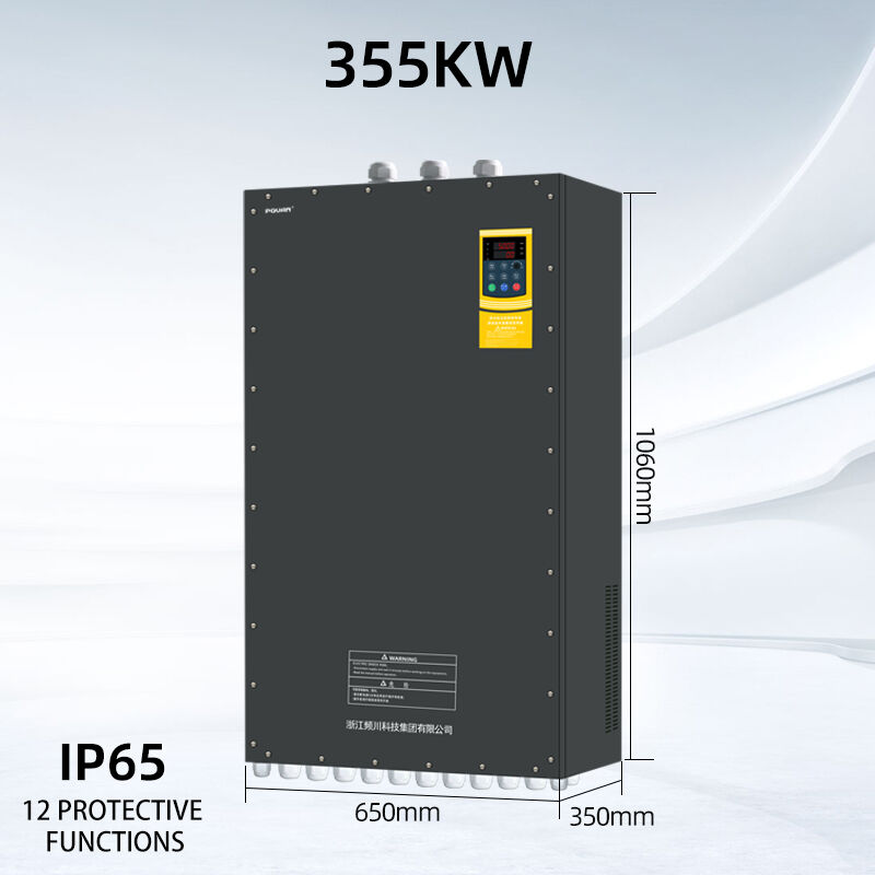
Installing a Variable Frequency Drive correctly is just as important as selecting the right one. A drive that is improperly wired, poorly mounted, or inadequately configured will underperform, trip on faults, and wear out far sooner than its rated service life. Whether you are retrofitting an existing motor system or commissioning a new installation, following a structured approach ensures the drive operates safely, efficiently, and reliably from day one.
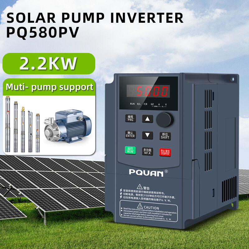
Understanding the Installation Environment
Before any wiring begins, the physical environment where the Variable Frequency Drive will be mounted must be carefully assessed. VFDs generate heat during operation and contain sensitive electronics that react to moisture, dust, vibration, and corrosive atmospheres. Choosing the wrong location — or failing to account for ambient conditions — is one of the most common causes of premature drive failure.
The drive should be mounted vertically on a flat, rigid surface inside a clean, dry enclosure. Adequate clearance above and below the unit is essential to allow cooling airflow to move through the heatsink fins without restriction. Most manufacturers specify a minimum of 100 mm clearance at the top and bottom. In environments with elevated ambient temperatures, additional forced ventilation or air conditioning within the control panel may be required to keep the drive within its operating temperature range, typically 0°C to 40°C for standard models.
For installations in dusty, humid, or chemically active environments — such as water treatment facilities, food processing plants, or coastal industrial sites — drives with a higher ingress protection rating should be selected to prevent contaminant ingress that degrades internal components over time.
Electrical Wiring and Power Connections
Correct electrical wiring is the foundation of a safe and reliable Variable Frequency Drive installation. The power circuit and control circuit must be treated as entirely separate systems, both in terms of cable routing and grounding.
On the power side, input terminals (R, S, T) connect to the incoming three-phase supply through a correctly rated circuit breaker or disconnect switch. Output terminals (U, V, W) connect directly to the motor. A critical rule is that no power factor correction capacitors, output contactors that switch under load, or other reactive components should be placed between the drive output and the motor terminals — the drive's PWM output waveform is incompatible with these devices and will cause damage or nuisance tripping.
Cable selection matters significantly at the output stage. To reduce electromagnetic interference (EMI) generated by the drive's switching frequency, shielded motor cable should be used between the drive and motor, with the cable shield bonded to the drive's PE terminal and the motor frame at both ends. This single measure eliminates the majority of interference-related issues reported in VFD installations.
| Wiring Rule | Reason |
|---|---|
| Separate power and control cable routes | Prevents EMI from inducing noise in signal wiring |
| Shielded motor cable (output side) | Reduces radiated EMI and conducted interference |
| No capacitors between drive output and motor | PWM waveform damages capacitors and causes faults |
| Dedicated earth/ground connection | Ensures personnel safety and stable drive operation |
| Input line reactor for drives >15 kW | Protects against voltage spikes and reduces harmonic distortion |
The control wiring — for analog speed references, digital start/stop commands, and relay outputs — should run in separate conduit or trunking, physically separated from power cables by at least 200 mm. Twisted-pair or shielded cable is recommended for analog signal wiring to prevent reference signal drift.
Grounding and EMC Compliance
Grounding is the aspect of VFD installation most frequently done incorrectly, yet it has the greatest impact on both safety and electromagnetic compatibility. The drive must have a dedicated, low-impedance earth connection run directly back to the main earthing point — not daisy-chained through other equipment.
For installations where EMC compliance is required — such as equipment sold into CE-marked markets or connected to sensitive instrumentation — an EMC filter should be fitted at the drive input. Many drives include an integrated EMC filter that can be activated by a configuration link, but in others it must be added externally. The filter is only effective when the drive enclosure and motor cable shield are properly bonded, reinforcing why grounding discipline cannot be treated as an afterthought.
Parameter Configuration and Motor Setup
Once wiring is complete and verified, the drive must be configured before the motor is energized. At minimum, the following motor nameplate data should be entered into the drive parameters: rated voltage, rated current, rated frequency, rated speed (RPM), and motor power. These values allow the drive's internal motor model to calculate correct slip compensation, current limiting, and thermal protection thresholds.
Acceleration and deceleration ramp times should be set to match the mechanical load. For high-inertia loads such as fans and centrifugal pumps, longer ramp times reduce mechanical stress and prevent DC bus overvoltage faults during deceleration. For conveyor or positioning applications, ramp times must be balanced against process cycle time requirements.
Carrier frequency — the switching frequency of the inverter output — affects both motor noise and drive losses. Higher carrier frequencies produce quieter motor operation but increase heat generation within the drive. A setting between 4 kHz and 8 kHz suits most general-purpose applications.
Pre-Commissioning Checks and First Run
Before applying power for the first time, a systematic pre-commissioning check should be completed. Verify that all power and control terminals are torqued to specification, that no tools or loose conductors remain inside the enclosure, and that the motor is mechanically uncoupled from the load if possible for initial testing.
Apply power without enabling the run command and confirm that the drive powers up without fault codes. Check the display for correct voltage readings and verify that parameter settings have been saved. Then issue a low-speed run command — typically 10 to 15 Hz — and confirm that motor rotation direction is correct before ramping to full operating speed. Phase rotation can be reversed at the drive output by swapping any two of the U, V, W output terminals, eliminating the need to rewire the motor itself.
Frequently Asked Questions
Q: Can a VFD be installed outdoors? Standard VFDs are designed for indoor, climate-controlled environments. Outdoor installation requires either a drive rated to IP54 or higher, or a weatherproof enclosure that maintains appropriate internal temperature and humidity conditions.
Q: How long should motor cables be between the drive and motor? Cable length affects the peak voltage seen at the motor terminals due to reflected wave effects. For most standard drives, cable runs up to 20–30 metres are unproblematic. Beyond 50 metres, an output reactor or dV/dt filter should be installed at the drive output to protect motor winding insulation.
Q: Is a dedicated circuit breaker required for each VFD? Yes. Each Variable Frequency Drive should be protected by its own correctly rated circuit breaker or fused disconnect. This ensures selective fault isolation and protects the drive's input rectifier components from short-circuit damage.
Q: Can the same VFD control multiple motors simultaneously? A single VFD can supply multiple motors connected in parallel, provided the drive is sized for the total combined motor current. However, individual motor overload protection must still be provided for each motor, as the drive's thermal model only monitors aggregate current.
Q: What is the most common cause of VFD failure after installation? Overheating due to inadequate ventilation is the leading cause of early drive failure. Ensuring sufficient clearance, clean cooling airflow, and ambient temperature within the drive's rated range will prevent the majority of thermally-induced faults.