 EN
EN

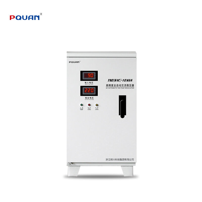
Fluctuations within low-voltage electrical distribution networks present a continuous hazard to high-value industrial machinery. Deploying an Automatic Voltage Regulator is the most effective strategy for neutralizing voltage sags, surges, and transient brownouts before they can disrupt your facility's operations. However, the protective capabilities and overall reliability of this precision equipment depend heavily on a physically secure and technically accurate installation process.
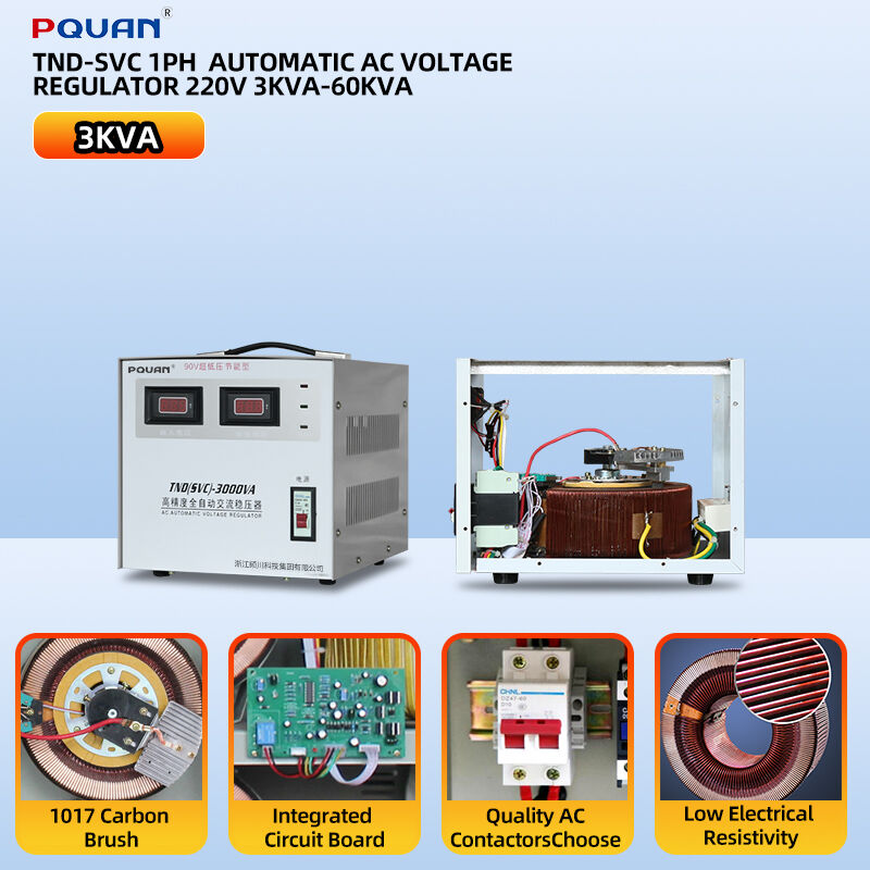
A proper installation ensures that your Automatic Voltage Regulator operates at peak efficiency, maintains exact voltage regulation accuracy, and functions safely under variable industrial loads. Whether you are safeguarding heavy-duty ventilation fans, automated conveyor networks, industrial air compressors, or high-volume water pumps, following a structured installation protocol prevents premature component failure and secures your long-term electrical infrastructure investment.
Pre-Installation Site Evaluation and Safety Preparation
Before unboxing your Automatic Voltage Regulator, you must thoroughly evaluate the intended installation environment. Because these systems contain heavy internal isolation transformers and sensitive microprocessor-controlled switching circuits, they generate heat during continuous voltage correction and require adequate cooling. The installation site must be a clean, dry, well-ventilated indoor space free from conductive dust, moisture accumulation, and corrosive chemical vapors. Ensure that the mounting surface can stably support the full weight of the enclosure and allows for the physical clearances recommended by the manufacturer to support natural air convection.
Safety is the absolute priority during any electrical integration process. Before initiating any physical work, isolate the main upstream circuit breaker supplying power to the installation area and verify that the line is completely dead using a certified, calibrated digital multimeter. Implement a strict lockout/tagout procedure at the distribution panel to prevent accidental re-energization while technicians are handling exposed wiring. Equipping your installation team with personal protective equipment, including insulated tools and arc-flash rated gear, is a mandatory preparatory step.
Heavy-Duty Mechanical Mounting and Physical Placement
Once the environment is prepped and power is safely isolated, position the regulator enclosure in its permanent location. If the unit is a floor-standing configuration, utilize industrial machinery rollers to guide it into place, ensuring it rests perfectly level on a vibration-resistant concrete foundation. For wall-mounted models, securely anchor the heavy-duty bracket into solid structural supports rather than simple drywall or light-gauge sheet metal, utilizing high-tensile fasteners capable of sustaining the unit’s weight over years of operational service.
After securing the enclosure mechanically, remove the front or lower access panels to expose the main internal terminal blocks and busbars. Inspect the internal components visually to ensure no wiring connections or circuit boards loosened during shipping. Pay close attention to the ventilation path, verifying that all external filters are seated correctly and that the top and side exhaust vents are completely unobstructed by nearby structural walls or adjacent electrical cabinets.
Precision Electrical Wiring and Terminal Torque Integration
The electrical wiring process requires careful alignment with the specific input and output parameters listed on the equipment nameplate. Begin by routing the main input and output power cables through the designated conduit knockouts on the base of the enclosure, utilizing appropriate strain-relief strain bushings to protect the cable insulation from sharp metal edges. You must utilize copper conductors correctly sized for the maximum continuous current capacity of the regulator, accounting for any potential voltage drop across long wire runs.
Connect the incoming main utility lines directly to the input terminals, maintaining strict phase consistency (Phase A, B, C, and Neutral) as indicated by the wiring schematics. Next, connect the downstream load distribution lines to the output terminals. The most critical step in the electrical sequence is establishing a solid, low-resistance system ground; connect the facility's main grounding bus directly to the regulator's primary ground terminal to ensure safety mechanisms can clear electrical faults. Finally, utilize a calibrated torque wrench to tighten every terminal screw to the manufacturer's exact torque specifications, preventing the loose connections that cause localized heating and terminal burnout.
System Configuration and Application Matching Matrix
Before energizing the system for production, technicians must verify that the regulator's internal settings correspond precisely with the technical requirements of the connected machinery. The evaluation matrix below outlines the ideal configuration focus areas across standard industrial equipment groups.
| Connected Equipment Type | Core Power Challenge | Recommended Regulator Setting | Technical Objective |
| Industrial Water Pumps | Severe voltage drops caused by high motor starting inrush currents. | High Surge Delay Tolerance | Prevents the system from triggering low-voltage trips during initial motor startup cycles. |
| HVAC Ventilation Fans | Continuous minor grid voltage drifting and line noise. | Precise Servo Regulation Profile | Delivers highly stable, smooth voltage correction to maintain uniform fan motor velocity. |
| Material Handling Conveyors | Sudden load shifts causing sharp current sags. | High Short-Term Overload Capacity | Sustains sudden mechanical load spikes without dropping line voltage to control sensors. |
| Air Compressors | Rapid cyclic loading causing localized harmonic feedback. | Microprocessor Fast Static Switching | Utilizes millisecond-level electronic tap adjustment to protect sensitive internal control boards. |
Initial Commissioning, Testing, and Verification Protocols
With all physical and electrical connections verified, close the internal circuit breakers and reattach all safety access panels. Remove the lockout/tagout devices from the main distribution panel and turn on the upstream source breaker to supply power to the regulator input. The digital display on the Automatic Voltage Regulator should illuminate immediately, executing a self-diagnostic sequence to verify internal control board integrity and phase orientation.
Observe the live data displayed on the screen, comparing the incoming utility line voltage against the stabilized output values. Utilize an external digital multimeter to measure the voltage directly at the output terminals, confirming that it matches both the display readouts and the required operating voltage of your industrial equipment. Once stable performance is verified without any unusual audible humming or heat signatures, activate the output bypass switch to safely deliver clean, regulated electrical power to your downstream facility assets.
Frequently Asked Questions
What is the purpose of the manual bypass switch on an Automatic Voltage Regulator?
The manual bypass switch is a critical engineering safety feature that reroutes incoming utility power directly to the downstream machinery, completely isolating the regulator's internal transformer and control circuits. This configuration allows maintenance teams to safely perform internal calibrations, cleanings, or component replacements without forcing a complete power shutdown of the connected production lines.
How do I accurately calculate the right capacity size for my regulator installation?
To size the unit properly, calculate the total volt-ampere (VA or kVA) consumption of all connected equipment by multiplying the maximum running current by the operational voltage. You must add a safety margin of at least twenty to thirty percent to this total to safely accommodate future facility expansions and the intense temporary inrush currents characteristic of large inductive electric motors.
Can this regulator be installed outdoors to protect exposed pumping stations?
Standard industrial regulators are manufactured with NEMA 1 or IP20 rated enclosures, which are engineered strictly for indoor protection against dust and contact. Installing a system outdoors requires a specialized weather-proof enclosure rated IP54 or higher, featuring integrated climate control or heavy-duty filtered ventilation to handle ambient humidity, driving rain, and extreme solar heating.
Why is periodic torque verification necessary after the initial installation?
Thermal cycling—the natural expansion and contraction of electrical conductors as they heat up under mechanical load and cool down when idle—gradually loosens terminal connections over time. Loose connections increase electrical resistance, leading to severe localized heat buildup, erratic voltage readouts, and eventual terminal failure if not checked with a torque wrench during annual maintenance.
Table of Contents
- Pre-Installation Site Evaluation and Safety Preparation
- Heavy-Duty Mechanical Mounting and Physical Placement
- Precision Electrical Wiring and Terminal Torque Integration
- System Configuration and Application Matching Matrix
- Initial Commissioning, Testing, and Verification Protocols
-
Frequently Asked Questions
- What is the purpose of the manual bypass switch on an Automatic Voltage Regulator?
- How do I accurately calculate the right capacity size for my regulator installation?
- Can this regulator be installed outdoors to protect exposed pumping stations?
- Why is periodic torque verification necessary after the initial installation?