
The electrical power delivered to our homes and industrial facilities is rarely as stable as it should be. Power grids constantly experience fluctuations, resulting in voltage sags, sudden surges, and brownouts that can permanently damage sensitive electronics or disrupt critical machinery. A voltage stabilizer acts as a reliable guardian between the erratic utility grid and your valuable equipment, ensuring a steady, safe supply of electricity.
For beginners and plant managers alike, understanding the mechanics behind this equipment is essential for protecting electrical investments. A high-quality voltage stabilizer does not just prevent immediate hardware burnout; it optimizes power quality, lowers long-term utility expenses, and ensures that automated systems run seamlessly without unexpected interruptions.
The Core Concept of Automatic Voltage Regulation
At its most fundamental level, a voltage stabilizer is designed to maintain a predetermined, constant output voltage regardless of how much the input voltage drops or spikes. It achieves this by continuously monitoring the incoming electrical current and comparing it against a safe, programmed reference value. If the incoming power deviates from this standard, the internal correction circuitry activates to bring the voltage back into equilibrium.
To visualize how this works, think of the stabilizer as an automated electrical valve. When the utility company experiences a voltage drop—often during hot summer months when air conditioning loads peak—the stabilizer detects this drop and boosts the voltage to the correct level. Conversely, if a sudden surge or lightning strike sends a dangerous spike through the lines, the system steps down the voltage instantly, neutralizing the hazard before it can reach your downstream machinery.
Demystifying the Internal Balancing Mechanisms
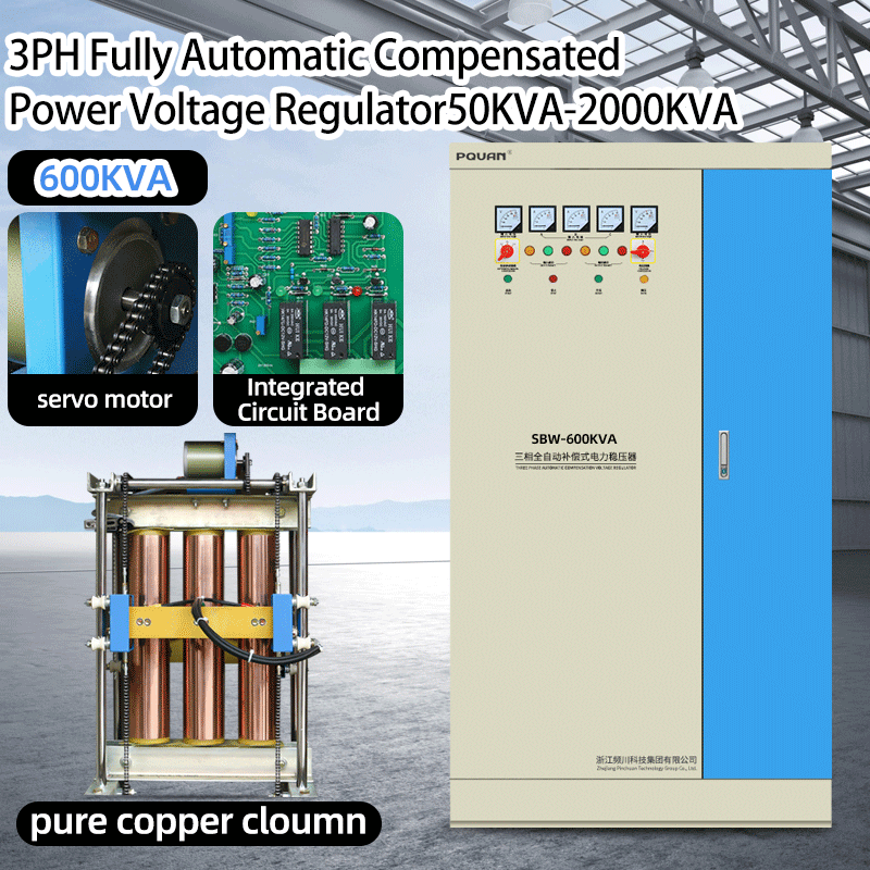
To understand how a voltage stabilizer performs this continuous balancing act, we must look at the two primary technologies used in modern industrial environments: servo-controlled systems and static electronic systems. Both rely on a specialized transformer architecture, but they control it using entirely different methods.
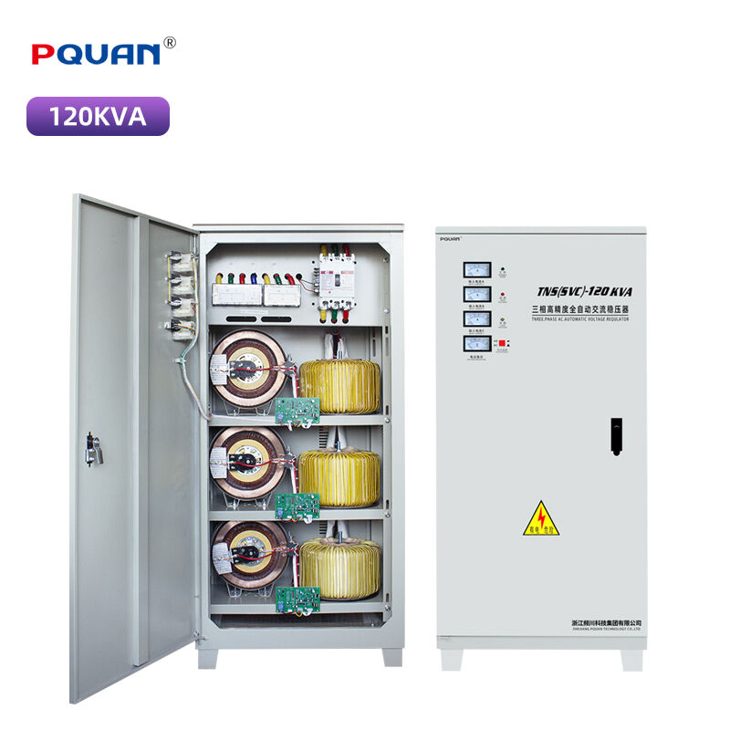
Servo-controlled stabilizers utilize an intelligent electronic control board connected to a motorized carbon brush assembly. When the input voltage changes, the control board commands a high-speed servo motor to physically move the carbon brush across the copper windings of a variable autotransformer. Shifting the brush position alters the turns ratio of the transformer, which either increases or decreases the voltage output. This method delivers exceptionally precise regulation, making it ideal for large facilities, industrial water pumps, and heavy-duty manufacturing lines.
Static voltage stabilizers, on the other hand, contain no moving parts. Instead of a motorized brush, they utilize high-power solid-state electronic switches, such as silicon-controlled rectifiers (SCRs) or insulated-gate bipolar transistors (IGBTs). These electronic switches alter the transformer connections instantly in response to digital microprocessors. Because there is no mechanical friction or wear, static stabilizers offer incredibly fast correction speeds, making them perfect for highly sensitive electronics, CNC machinery, and high-frequency automated conveyors.
Strategic Selection Matrix Across Industry Applications
Choosing the right stabilizer technology depends heavily on your specific operational environment and mechanical loads. The table below outlines how different stabilization features align with common industrial applications to guide your engineering decisions.
| Target Application | Dominant Power Challenge | Recommended Stabilizer Feature | Technical Justification |
| Industrial Water Pumps | Severe voltage drops during motor startup cycles. | High Surge Current Sustenance | Absorbs high inrush currents without tripping or dropping line voltage. |
| HVAC Ventilation Fans | Continuous grid voltage fluctuations. | Servo Motorized Precision | Delivers smooth, step-less voltage adjustments to maintain stable motor speeds. |
| Material Handling Conveyors | Sudden mechanical load shifts causing voltage sags. | High Overload Capacity | Sustains temporary current spikes when heavily loaded belts begin moving. |
| Air Compressors | Rapid cyclic loading causing local grid instability. | Microprocessor-Controlled Static Regulation | Corrects voltage fluctuations instantly to protect sensitive pressure sensors and control boards. |
Maintenance Foundations for Long-Term Reliability
An industrial-grade voltage stabilizer is built for durability, but it requires regular preventative maintenance to guarantee a long operational lifespan. Over time, thermal cycling can cause internal electrical terminals to loosen, creating localized resistance and heat buildup. Scheduled shutdowns should always include torqueing all power input and output terminal connections to prevent terminal burnout.
Environmental cleanliness is equally critical. For servo-based models, the movement of the carbon brush naturally generates a fine carbon film over time. Maintenance technicians must periodically isolate the unit from power and use non-conductive tools to clean the copper commutator surface. Furthermore, ensuring that ventilation filters are kept free of dust prevents thermal overloading, ensuring your stabilizer delivers clean, uncorrupted power for years to come.
Frequently Asked Questions
What is the primary difference between a voltage stabilizer and a VFD drive?
While both manage electrical power for industrial machinery, they serve completely different functions. A stabilizer corrects incoming grid voltage fluctuations to provide a steady 50Hz or 60Hz power supply to standard equipment. A variable frequency drive (VFD), conversely, is a specialized motor controller that actively changes both the voltage and the frequency output to vary the operating speed and torque of an AC motor.
How do I accurately calculate the correct stabilizer capacity for my facility?
To size a stabilizer properly, you must calculate the total volt-ampere (VA or kVA) rating of all connected equipment. Multiply the operating voltage by the total maximum current drawn by your machinery, and add a safety margin of at least twenty to thirty percent to accommodate future expansion and the high starting inrush currents characteristic of large electric motors.
Can a voltage stabilizer also clean up electrical line noise?
Standard stabilizers are designed primarily to fix slow voltage sags and surges. However, high-quality industrial models often feature integrated isolation transformers, line reactors, or dedicated radio frequency interference (RFI) filters. These advanced components help suppress high-frequency harmonic noise and electromagnetic interference, protecting sensitive digital control systems.
What happens if the incoming grid voltage drops completely outside the stabilizer's working range?
Every stabilizer has a defined input window, such as plus or minus twenty percent of nominal voltage. If the grid drops below or spikes above this threshold, the stabilizer's internal control microprocessor will trigger an automatic low-voltage or high-voltage trip. This immediately disconnects the output power to completely shield downstream equipment from extreme, uncorrectable power anomalies.
Table of Contents
- The Core Concept of Automatic Voltage Regulation
- Demystifying the Internal Balancing Mechanisms
- Strategic Selection Matrix Across Industry Applications
- Maintenance Foundations for Long-Term Reliability
-
Frequently Asked Questions
- What is the primary difference between a voltage stabilizer and a VFD drive?
- How do I accurately calculate the correct stabilizer capacity for my facility?
- Can a voltage stabilizer also clean up electrical line noise?
- What happens if the incoming grid voltage drops completely outside the stabilizer's working range?