 EN
EN

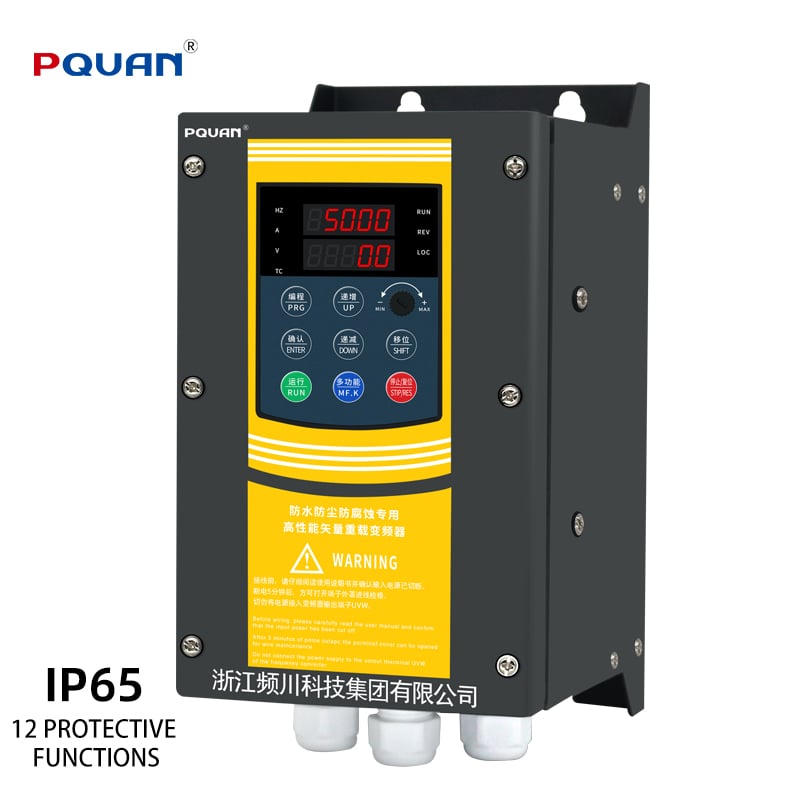
A frequency inverter is one of the most important pieces of power control technology in modern industrial operations. Whether you are running a conveyor system, a pump, a compressor, or a fan, the ability to precisely regulate motor speed directly determines how efficiently your equipment performs. Understanding how a frequency inverter works is not just a technical exercise — it is a practical foundation for making smarter decisions about energy consumption, equipment longevity, and process control in any facility that relies on AC motors.
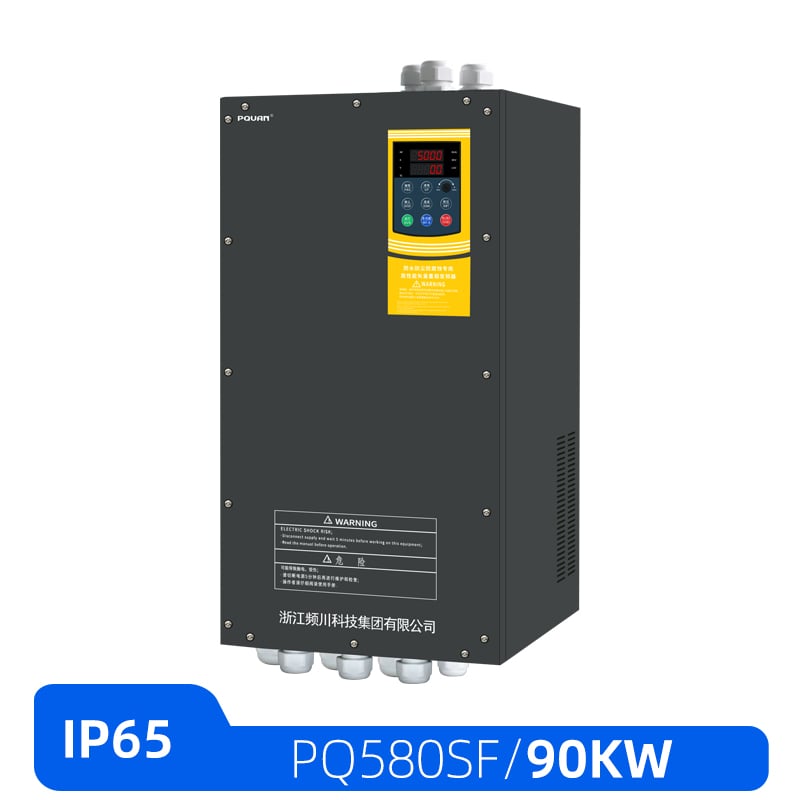
The core mechanism of a frequency inverter revolves around converting fixed-frequency AC power into a variable-frequency, variable-voltage output that the motor can respond to dynamically. This process enables operators to match motor output precisely to the actual load demand at any given moment, rather than running the motor at full speed regardless of need. The result is a system that is both more responsive and significantly more energy-efficient than traditional fixed-speed motor control methods. This article walks through the internal working principles, the energy-saving logic, and the practical application context of the frequency inverter in detail.
The Internal Working Mechanism of a Frequency Inverter
Rectification: Converting AC to DC
The first stage inside a frequency inverter is the rectifier circuit. Incoming AC power from the grid — typically at a fixed frequency of 50 Hz or 60 Hz depending on the region — is fed into a bridge rectifier made up of diodes or thyristors. This rectifier converts the alternating current into a raw, pulsating direct current. The conversion is a necessary first step because the inverter needs a stable DC bus to work from before it can generate a new, controllable AC output.
After rectification, the pulsating DC passes through a filter stage, usually consisting of large capacitors and sometimes inductors. These components smooth out the voltage ripple and create a stable DC link voltage. This DC bus is the energy reservoir from which the output stage draws power. The quality and stability of this DC bus directly affect the performance and reliability of the entire frequency inverter system, which is why the filter design is a critical engineering consideration in any industrial-grade unit.
Inversion: Generating Variable-Frequency AC Output
The second and most defining stage of a frequency inverter is the inverter stage itself. This is where the DC bus voltage is converted back into AC, but now at a frequency and voltage level that the control system determines. The inverter stage uses power semiconductor switches — most commonly Insulated Gate Bipolar Transistors, or IGBTs — arranged in a three-phase bridge configuration. By switching these transistors on and off at precisely timed intervals, the inverter synthesizes a simulated AC waveform.
The switching pattern used in virtually all modern frequency inverter designs is called Pulse Width Modulation, or PWM. In PWM control, the IGBTs switch at a high carrier frequency — typically between 2 kHz and 16 kHz — and the width of each pulse is varied to approximate a smooth sinusoidal waveform. The motor's own inductance acts as a natural filter, smoothing the pulsed output into a near-sinusoidal current that drives the rotor. By changing the frequency of the PWM pattern, the frequency inverter directly controls the rotational speed of the motor. By simultaneously adjusting the output voltage in proportion to the frequency, it maintains the correct magnetic flux in the motor across the entire speed range.
This voltage-to-frequency ratio control, often called V/F or V/Hz control, is the most widely used control mode in general-purpose frequency inverter applications. More advanced units also support vector control modes — either open-loop sensorless vector control or closed-loop flux vector control with encoder feedback — which provide much tighter torque and speed regulation for demanding applications such as hoists, winders, and precision machine tools.
How a Frequency Inverter Controls Motor Speed
The Relationship Between Output Frequency and Motor Speed
The synchronous speed of an AC induction motor is directly determined by the frequency of the power supply and the number of magnetic poles in the motor winding. The standard formula is straightforward: synchronous speed in RPM equals 120 times the supply frequency divided by the number of poles. This means that if a frequency inverter reduces the output frequency from 50 Hz to 25 Hz, the motor's synchronous speed is cut in half. Conversely, increasing the output frequency above the base frequency allows the motor to run faster than its nameplate speed, a mode known as field weakening operation.
This direct, linear relationship between output frequency and motor speed is what makes the frequency inverter such a powerful and precise control tool. Unlike mechanical speed reduction methods such as gearboxes or belt drives, the frequency inverter achieves speed variation electronically, with no additional mechanical wear, no lubrication requirements, and no physical adjustment needed. Speed changes can be made in real time through analog signals, digital inputs, fieldbus communication, or the drive's own keypad, giving operators full flexibility in how they manage process speed.
Acceleration, Deceleration, and Torque Management
One of the most practically valuable aspects of a frequency inverter is its ability to control how quickly a motor accelerates and decelerates. In a direct-on-line start, an AC motor draws a starting current that can be six to eight times its rated full-load current. This inrush causes mechanical stress on the motor windings, the shaft, the coupling, and the driven load. A frequency inverter eliminates this problem entirely by starting the motor at a low frequency and gradually ramping up to the target speed over a programmable acceleration time.
The same logic applies to stopping. A frequency inverter can decelerate the motor in a controlled ramp rather than allowing it to coast to a stop or applying a sudden brake. For applications like conveyors carrying fragile products, or pumps where water hammer is a concern, this controlled deceleration is not just a convenience — it is a process requirement. Some frequency inverter models also support DC injection braking or dynamic braking with a braking resistor, providing additional stopping force when the application demands it.
Energy Savings Through Variable Speed Control
The Affinity Laws and Their Impact on Power Consumption
The energy-saving potential of a frequency inverter is most dramatic in centrifugal load applications such as pumps, fans, and blowers. These loads follow the affinity laws of fluid dynamics, which describe a cubic relationship between speed and power consumption. Specifically, the power required by a centrifugal pump or fan is proportional to the cube of its rotational speed. This means that reducing the motor speed to 80 percent of its rated speed reduces the power demand to approximately 51 percent — a reduction of nearly half the energy consumption for a relatively modest speed reduction.
In facilities where pumps or fans run continuously but rarely need to operate at full capacity, the energy savings from installing a frequency inverter can be substantial. Many industrial operations report payback periods of one to three years on frequency inverter installations based on electricity savings alone. Over the full service life of the equipment, the cumulative energy cost reduction often far exceeds the initial investment in the drive system. This is why energy efficiency regulations in many regions now mandate or incentivize the use of variable speed drives in large pump and fan installations.
Eliminating Throttling Losses and Improving System Efficiency
Before variable speed drives became widely available, the standard method for controlling flow in pump and fan systems was throttling — using valves or dampers to restrict flow while the motor continued to run at full speed. This approach is inherently wasteful because the motor is still consuming near-full power while the throttling device dissipates energy as heat or pressure drop. A frequency inverter eliminates this waste by reducing the motor speed to match the actual flow requirement, so the system only consumes the energy it genuinely needs.
Beyond the direct energy savings, running motors at reduced speeds through a frequency inverter also reduces heat generation in the motor windings, lowers bearing loads, and decreases vibration and acoustic noise. All of these factors contribute to longer motor service life and reduced maintenance costs. In large facilities with dozens of motors, the aggregate maintenance savings from reduced wear can be a significant secondary benefit of a comprehensive frequency inverter deployment strategy.
Practical Application Scenarios for a Frequency Inverter
Pumps, Fans, and HVAC Systems
The most common application for a frequency inverter in industrial and commercial settings is variable flow control in pump and fan systems. Water supply pumps in buildings can use a frequency inverter with a pressure sensor in a closed-loop PID control configuration to maintain constant system pressure regardless of demand fluctuations. As more outlets open and demand increases, the drive speeds up the pump. As demand drops, it slows the pump down. The result is stable pressure, minimal energy waste, and reduced mechanical stress on the entire piping system.
In HVAC applications, air handling units and cooling tower fans benefit enormously from frequency inverter control. Ambient temperature and occupancy levels vary throughout the day, meaning that a fan running at full speed continuously is almost always consuming more energy than necessary. A frequency inverter allows the fan speed to track actual thermal load, maintaining comfort conditions while minimizing electricity consumption. This is one of the most cost-effective energy management strategies available to building operators and facility managers.
Compressors, Conveyors, and Machine Tools
In compressor applications, a frequency inverter enables the compressor motor to modulate its speed in response to system pressure demand rather than cycling on and off at full speed. This eliminates the energy-intensive repeated starting cycles, reduces pressure fluctuations in the compressed air network, and extends the service life of the compressor valves and mechanical components. For operations that rely on a stable compressed air supply, the process quality improvement alone can justify the investment in a frequency inverter.
Conveyor systems benefit from the smooth start and stop capability of a frequency inverter, particularly when handling fragile or unstable loads. Machine tool spindles use frequency inverter drives to achieve precise speed control across a wide range, enabling a single machine to handle different materials and cutting operations without mechanical gear changes. In each of these scenarios, the frequency inverter serves as the central intelligence layer between the power supply and the motor, translating process requirements into precise electrical output.
Key Selection Considerations for a Frequency Inverter
Matching Drive Capacity to Motor and Load Type
Selecting the right frequency inverter begins with accurately characterizing the motor it will drive and the nature of the load. The drive's current rating must be sufficient to handle both the continuous running current and any overload current that the application may demand. For constant torque loads such as conveyors and positive displacement pumps, the drive must be rated for 150 percent overload capacity for short durations. For variable torque loads such as centrifugal pumps and fans, a lighter overload rating is typically acceptable, and a drive sized for variable torque duty may offer cost advantages.
The supply voltage must also match the drive's input specification. A frequency inverter designed for three-phase 380V input cannot be connected to a single-phase 220V supply without derating or modification. Many modern drives are available in both single-phase input and three-phase input variants to accommodate different installation environments. Always verify the input voltage range, the output voltage range, and the rated output current before specifying a frequency inverter for any application.
Environmental Ratings, Protection Class, and Installation Requirements
The operating environment has a significant influence on which frequency inverter is appropriate for a given installation. Drives installed in clean, temperature-controlled electrical rooms can use standard IP20 enclosures. Drives installed in dusty, humid, or chemically aggressive environments require higher ingress protection ratings such as IP54 or IP65. Some applications require the drive to be mounted directly on the motor as a 'drive-on-motor' unit, which demands a compact, ruggedized design capable of withstanding vibration and temperature extremes.
Thermal management is another critical installation consideration. A frequency inverter generates heat during operation, and adequate ventilation or forced cooling must be provided to keep the drive within its rated operating temperature range. Derating curves published by the manufacturer specify how the drive's output capacity must be reduced at elevated ambient temperatures or high altitudes where air density is lower. Ignoring these derating requirements is one of the most common causes of premature frequency inverter failure in field installations.
FAQ
What is the difference between a frequency inverter and a standard motor starter?
A standard motor starter connects the motor directly to the fixed-frequency grid supply and provides only on/off control with limited soft-start capability. A frequency inverter generates a fully variable output frequency and voltage, enabling continuous speed control across the motor's entire operating range. This makes the frequency inverter far more capable in terms of energy management, process control, and motor protection compared to any type of conventional starter.
Can a frequency inverter be used with any AC motor?
A frequency inverter is compatible with standard squirrel-cage induction motors in the vast majority of applications. However, when operating at very low speeds for extended periods, standard motors may experience reduced cooling effectiveness since their shaft-mounted cooling fans slow down with the motor. In such cases, motors with separate forced ventilation or motors specifically designed for inverter duty should be used. Permanent magnet synchronous motors also work with frequency inverter drives but require a drive that supports the appropriate control algorithm for that motor type.
How does a frequency inverter contribute to energy savings in real operations?
The energy savings from a frequency inverter come primarily from matching motor speed to actual load demand rather than running at full speed continuously. In centrifugal pump and fan applications, the cubic relationship between speed and power means that even modest speed reductions produce large energy savings. In addition, the frequency inverter eliminates the high inrush current of direct-on-line starting, reduces reactive power demand, and allows the system to avoid energy-wasting throttling methods, all of which contribute to measurable reductions in electricity consumption and operating costs.
What maintenance does a frequency inverter require?
A frequency inverter is largely a solid-state device with no moving parts in the power electronics, which makes it inherently low-maintenance compared to mechanical speed control systems. The main maintenance tasks involve keeping the cooling fans and heat sink fins clean and free of dust accumulation, periodically checking the DC bus capacitors for signs of aging, verifying that all power and control terminal connections remain tight, and reviewing the drive's fault log for any recurring alarms that may indicate developing issues. Following the manufacturer's recommended maintenance schedule ensures that the frequency inverter delivers reliable service throughout its intended service life.