 EN

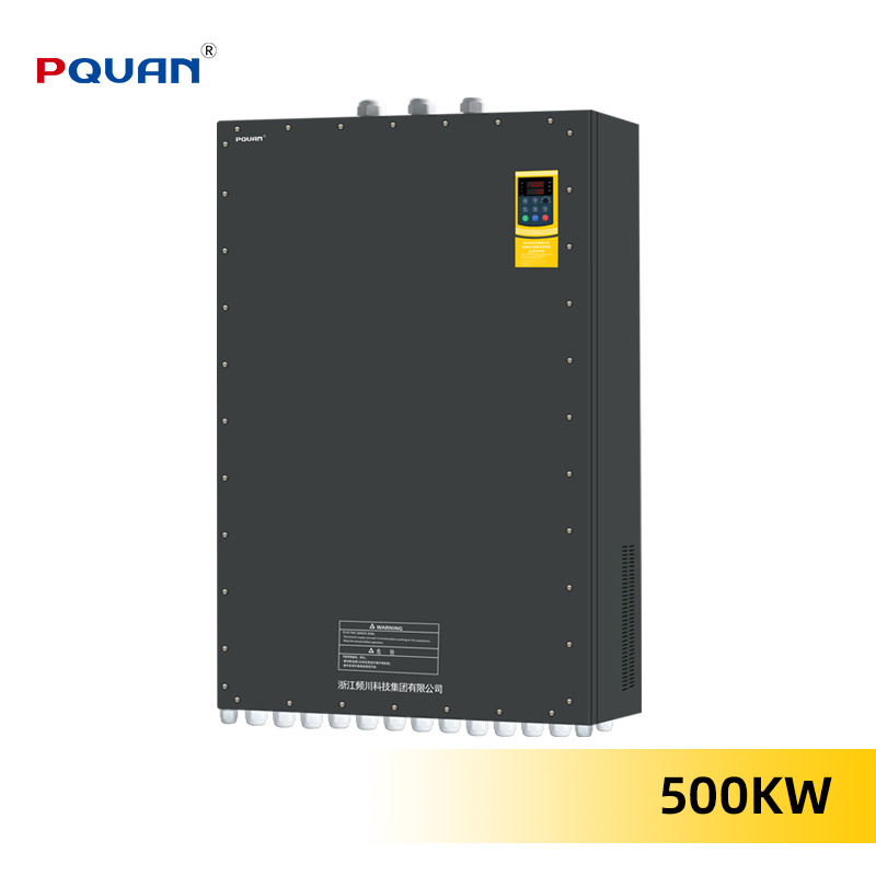
An inverter is essential equipment in modern industrial and commercial applications, converting DC power to AC power while managing motor speed and energy efficiency. When an inverter malfunctions, production can halt, leading to significant downtime and financial loss. Understanding common inverter problems and learning how to troubleshoot them effectively can help you identify issues quickly, minimize operational disruptions, and extend your inverter equipment lifespan. This guide explores the most frequent inverter challenges, their underlying causes, and practical troubleshooting approaches that facility managers and technicians can implement immediately.
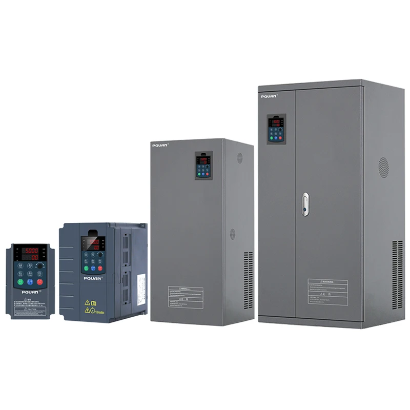
Inverter problems range from minor display errors to critical faults that prevent equipment operation entirely. The most common inverter issues involve thermal management, electrical connections, control signal interpretation, and component degradation. By mastering the fundamentals of inverter diagnostics, you gain the ability to perform preliminary checks before calling service technicians, potentially saving hours of downtime and reducing maintenance costs significantly. This knowledge also helps you communicate more effectively with specialists, describing symptoms accurately and accelerating the resolution process.
Common Inverter Failure Modes and Detection
Thermal Overload and Cooling Issues
Overheating stands as one of the most prevalent inverter problems affecting industrial operations. An inverter generates heat during normal operation, particularly under high-load conditions, and relies on adequate cooling through internal fans or external cooling systems. When ambient temperature rises excessively, cooling airflow becomes restricted, or the inverter radiator accumulates dust and debris, thermal stress accumulates rapidly. Many inverter failure incidents result from insufficient ventilation around the equipment or blocked intake vents. If your inverter displays temperature warnings or shuts down intermittently, thermal issues represent likely culprits requiring immediate inspection.
Troubleshooting inverter thermal problems begins with verifying the surrounding environment. Check that the inverter mounting location maintains proper clearance from walls and obstructions, allowing adequate air circulation around the cooling fans. Inspect the radiator fins for accumulated dust, debris, or insect contamination and clean them gently using compressed air if needed. Ensure the ambient temperature remains within the inverter manufacturer's specified operating range, typically between 0 and 40 degrees Celsius for most industrial inverters. If thermal shutdowns persist despite adequate cooling, internal component degradation may have occurred, warranting professional service inspection.
Electrical Connection and Input Power Problems
Inadequate or unstable power supply causes numerous inverter malfunctions that operators frequently misinterpret as equipment defects. An inverter requires stable three-phase or single-phase input voltage within narrow tolerance ranges, typically plus or minus ten percent of nominal voltage. Loose terminal connections, corroded contacts, or undersized power cables create voltage drops that starve the inverter of adequate input power, triggering protection circuits and fault codes. Many industrial facilities experience intermittent inverter problems linked to aging electrical infrastructure, poor grounding, or sharing circuits with other high-power equipment that causes voltage fluctuations.
Begin troubleshooting electrical connection issues by verifying input voltage using a multimeter, comparing actual readings against the inverter nameplate specifications. Inspect all power terminal connections for visible corrosion, discoloration, or loose clamps, then tighten connections carefully using appropriate tools. Examine the power cable for damage, crushed sections, or insulation deterioration that might cause partial shorts or leakage currents. Check that proper grounding connections exist between the inverter frame and facility ground bus, as poor grounding causes noise that corrupts control signals. If input power testing reveals voltages outside acceptable ranges, contact your electrical utility or facility maintenance team to investigate upstream supply stability issues before concluding the inverter itself has failed.
Troubleshooting Display Errors and Control Signal Issues
Fault Codes and Error Message Interpretation
Modern inverter control systems display alphanumeric fault codes when operational anomalies occur, providing valuable diagnostic information if properly interpreted. Common inverter error messages include overcurrent faults, overvoltage conditions, ground faults, communication timeouts, and temperature warnings. Each fault code corresponds to specific system conditions, and understanding these messages accelerates problem diagnosis significantly. Documentation accompanying your inverter equipment contains a complete fault code reference guide that technicians should consult immediately when unfamiliar codes appear. Many operators delay maintenance actions because they misunderstand or ignore displayed inverter warnings, allowing problems to escalate into critical failures.
When an inverter displays a fault code, first consult the equipment manual to identify what condition triggered that specific message. Record the exact code displayed, any accompanying text, and the approximate time the fault occurred relative to operational events. Note whether the fault appears consistently or intermittently, as this distinction narrows down potential causes significantly. Attempt a controlled reset by switching the inverter off, waiting thirty seconds, then restarting, which often clears temporary faults caused by brief disturbances. If the fault code reappears immediately after reset, the underlying condition persists and requires systematic investigation rather than repeated restart attempts.
Communication and Signal Cable Failures
Control signals transmitted between programmable controllers and the inverter through dedicated communication cables face constant vulnerability to electrical noise, physical damage, and connector corrosion. An inverter requires clean, undistorted control signals to interpret speed commands correctly and maintain stable operation. Signal cable routing near high-current power conductors exposes the communication lines to electromagnetic interference that corrupts transmitted data. Similarly, pinched cables, kinked sections, or connectors exposed to moisture create intermittent contact problems that generate mysterious fault codes and erratic inverter behavior. These inverter signal issues often defy simple troubleshooting because problems appear and disappear unpredictably depending on environmental conditions and equipment states.
Inspect all signal cables connected to the inverter for visible physical damage, including cuts, abrasions, or crushed sections that compromise conductor insulation. Separate control signal cables from high-power electrical lines by at least twelve inches to minimize electromagnetic interference affecting an inverter's reception of commands. Verify that connector pins remain clean and undamaged by gently inserting and removing connectors several times to enhance contact surfaces, then reinstalling them firmly until you feel positive mechanical engagement. Test the cable route for any sharp bends or stress points where the cable might flex repeatedly during equipment vibration. If intermittent inverter faults persist despite cable inspection, the internal shielding or conductors may have degraded, requiring cable replacement with properly shielded communication-grade conductors specified by the inverter manufacturer.
Advanced Diagnostics and Performance Optimization
Motor Loading and Speed Command Verification
An inverter operates optimally only when connected to appropriate motor loads and receiving valid speed command signals that align with actual operating requirements. Excessive motor load demands force the inverter to supply maximum current continuously, generating heat that approaches thermal shutdown thresholds. Undersized inverters connected to oversized motors struggle with startup inrush currents that repeatedly trigger overcurrent protections, preventing the system from reaching normal operation. Many inverter problems stem not from equipment malfunction but from fundamental mismatch between the drive capacity and the connected load. Careful verification of motor nameplate power ratings against inverter capacity ratings reveals whether adequate headroom exists for normal operation with safety margins.
Review the motor nameplate specifications and compare the listed kilowatt or horsepower rating against your inverter's rated output capacity, which should exceed motor requirements by at least twenty percent. Verify that the speed command signal transmitted to the inverter corresponds to desired motor speeds within the equipment's specified range, typically zero to one hundred percent of base speed. Examine motor current draw during operation using a multimeter or clamp meter, confirming that actual current remains below the inverter's maximum output rating at all operating points. If the motor load fluctuates dramatically, programmable logic controller settings may require adjustment to smooth the speed command ramp rates, preventing the inverter from hunting between speed setpoints. Some inverter problems resolve simply by optimizing acceleration and deceleration time settings to match the mechanical load characteristics, reducing stress on electrical components.
Maintenance and Preventive Care Practices
Systematic preventive maintenance reduces inverter problems by addressing component aging and environmental degradation before failures occur. Scheduled inspections should include visual examination of terminal connections for corrosion, verification of cooling fan operation and cleanliness, and confirmation that mounting location maintains proper environmental conditions. Electrolytic capacitors inside the inverter degrade gradually over years of operation, reducing their effectiveness and contributing to voltage stability problems that trigger mysterious faults. Most modern inverters contain replaceable component modules that facility technicians can swap during planned maintenance windows, restoring performance without waiting for specialized service technicians. Documentation of all inverter problems, repair actions, and maintenance interventions builds historical records that reveal patterns and help predict future issues before they impact production.
Establish quarterly cleaning routines for external radiator surfaces and intake vents, removing dust accumulation that progressively reduces cooling efficiency throughout the year. Monitor and record operating temperatures and fault event frequencies over extended periods to identify trending patterns indicating imminent failures. Test electrical input stability monthly using voltage meters to confirm supply remains within acceptable ranges, investigating any deviations with facility maintenance teams. Consider upgrading to advanced inverter models featuring enhanced diagnostic capabilities, superior thermal management, and redundant protection circuits that prevent common failure modes. Investing in superior inverter technology reduces long-term maintenance burdens and improves facility reliability significantly across the operational lifetime.
FAQ
What causes an inverter to stop working suddenly without displaying error codes?
An inverter ceasing operation without displaying codes often results from input power loss, tripped thermal protection resetting internally without visible indication, or communication cable disconnection that prevents control signal reception. Begin troubleshooting by verifying that adequate input power reaches the inverter terminals, checking all cable connections for looseness, and examining environmental temperature conditions. If no obvious electrical issue exists, internal component failure affecting the display circuit itself may prevent messages from appearing even though the protection system activated. Allow the inverter to cool for fifteen minutes in a safe state, then attempt restart to determine if thermal protection triggered the shutdown automatically.
How can facility staff reduce inverter maintenance costs through proactive measures?
Reducing inverter maintenance costs requires implementing preventive care routines that address environmental factors and electrical supply stability before problems develop. Maintain optimal ambient temperature and humidity conditions around the inverter installation location, as environmental stress accelerates component degradation more than any operational factor. Verify electrical input supply stability monthly to ensure voltage remains within manufacturer specifications, investigating deviations immediately rather than allowing unstable power to accumulate damage over time. Schedule quarterly equipment inspections documenting thermal performance, connection integrity, and fault event frequency, enabling facility staff to recognize developing problems and plan maintenance during convenient production windows rather than responding to emergency failures.
When should an inverter be replaced rather than repaired after troubleshooting fails?
Replace an inverter when repair costs exceed fifty percent of new equipment pricing, when internal component failures require parts unavailable for aging models, or when systematic troubleshooting across multiple sessions reveals persistent problems suggesting cumulative wear throughout the device. Inverters exceeding ten years of operational life typically exhibit increasing failure frequency as capacitors degrade, mechanical components wear, and control circuit elements become unreliable. Modern inverter technology provides superior efficiency, enhanced diagnostic capabilities, and improved thermal management compared to legacy equipment, often justifying replacement through reduced operational costs despite initial capital investment. Consult your equipment supplier or service provider when uncertain about repair versus replacement economics for specific failure scenarios.