 EN
EN

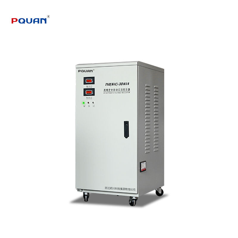
Choosing the wrong size automatic voltage regulator is one of the most common — and costly — mistakes in power protection planning. An undersized unit will overload under normal operating conditions, while an oversized one wastes capital and takes up unnecessary space. Getting the sizing right means understanding your equipment's actual power demands, the nature of your electrical loads, and the voltage stability requirements of the devices you are protecting. This guide walks through the key considerations so you can match the right voltage regulator to your specific application with confidence.
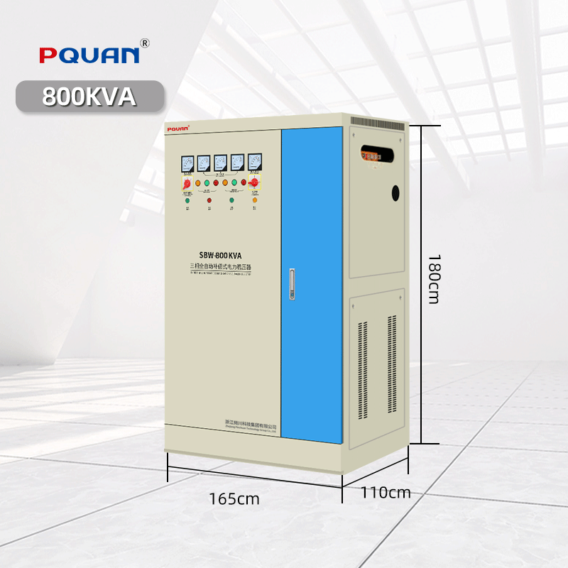
What Does an Automatic Voltage Regulator Actually Do?
A voltage regulator continuously monitors incoming supply voltage and corrects deviations — both high and low — to deliver a stable, regulated output to connected equipment. In real-world power environments, supply voltage rarely stays perfectly constant. Grid fluctuations, load switching by neighboring facilities, long distribution runs, and generator-based supplies all introduce voltage variations that can damage sensitive electronics, reduce motor efficiency, and shorten equipment lifespan.
An automatic voltage regulator addresses this by using a servo-motor or electronic switching mechanism to adjust a variable transformer in real time, maintaining output voltage within a tight tolerance band — typically ±2% to ±5% of the nominal setting — regardless of what the incoming supply is doing. This makes the voltage regulator an essential piece of infrastructure for any facility where voltage instability is a documented problem or where connected equipment has strict supply requirements.
Step One: Calculate Your Total Connected Load
The starting point for sizing any voltage regulator is an accurate calculation of the total power drawn by all equipment the unit will protect. This is expressed in kilovolt-amperes (kVA) rather than kilowatts (kW), because the voltage regulator must handle the apparent power of the load — which includes both real power and reactive power drawn by motors, transformers, and other inductive devices.
For resistive loads such as heaters and incandescent lighting, kVA and kW are effectively equal. For motor-driven equipment and other inductive loads, the power factor — typically between 0.7 and 0.9 for industrial motors — means that the kVA demand is higher than the kW figure on the nameplate. Always divide rated kW by the power factor to arrive at the true kVA demand before sizing.
| Load Type | Typical Power Factor | kVA Calculation Method |
|---|---|---|
| Resistive (heaters, lighting) | 1.0 | kVA = kW |
| AC induction motors | 0.75 – 0.85 | kVA = kW ÷ Power Factor |
| Mixed industrial loads | 0.7 – 0.85 | Sum individual kVA values |
| CNC machines / precision equipment | 0.8 – 0.9 | kVA = kW ÷ Power Factor |
| Medical / laboratory equipment | 0.85 – 0.95 | Refer to equipment nameplate |
Once you have the total kVA demand of all connected loads, add a safety margin of 20% to 25% to account for startup surges, future load additions, and to prevent the regulator from running continuously at or near its rated capacity — a practice that accelerates wear.
Step Two: Account for Motor Starting Currents
Motor starting current is the factor most frequently overlooked when sizing a voltage regulator, and it is the one most likely to cause an undersized unit to trip or fail. When an AC motor starts across the line, it draws an inrush current typically five to eight times its rated running current for the first few seconds of acceleration. During this period, the apparent power demand on the voltage regulator spikes dramatically.
If your protected equipment includes pumps, compressors, conveyors, fans, or any other motor-driven machinery, the voltage regulator must be sized to handle this starting surge without entering overload. As a practical rule, if a single large motor represents the dominant load, size the voltage regulator to at least twice the motor's running kVA to accommodate the starting transient comfortably. Where multiple motors may start simultaneously — as in some HVAC systems or production lines — the combined starting surge must be factored in.
This is also where the choice of voltage regulator type matters. Servo-motor based regulators offer high correction capacity and handle sustained overloads well, making them well-suited to motor-heavy applications. For facilities with frequent motor starts and stops, confirming the regulator's overload tolerance rating with the manufacturer is a prudent step before finalizing selection.
Step Three: Match the Regulator to Your Input Voltage Range
A voltage regulator can only correct voltage deviations within its designed input range. If your supply voltage fluctuates beyond that window, the regulator will reach the limit of its correction range and output voltage will begin to track the input — defeating the purpose of the device entirely.
Standard voltage regulators are designed for input ranges such as ±15%, ±20%, or ±25% of nominal voltage. In areas with stable grid infrastructure, a ±15% input range is generally sufficient. In regions with weak grid connections, generator-dependent supplies, or long rural distribution runs where voltage sag and swell are more pronounced, selecting a unit with a wider input range — ±20% or greater — provides the necessary headroom to maintain regulated output under all foreseeable conditions.
| Input Voltage Range | Suitable Application |
|---|---|
| ±10% | Urban grid with stable supply |
| ±15% | Standard industrial and commercial use |
| ±20% | Areas with moderate grid instability or generator supply |
| ±25% or wider | Remote sites, weak grid, tropical/developing regions |
Matching the input range to the actual voltage conditions at your site is as important as matching the kVA rating to your load.
Step Four: Single-Phase or Three-Phase Selection
The final sizing dimension is phase configuration. Single-phase voltage regulators are appropriate for residential applications, small office environments, and individual pieces of equipment rated for single-phase supply. Three-phase regulators are required for industrial motors, large HVAC systems, production machinery, and any three-phase distribution board.
For three-phase installations, it is also important to verify whether the load is balanced or unbalanced. In facilities where single-phase loads are spread unevenly across phases, a three-phase regulator with independent per-phase regulation provides superior voltage balance compared to a unit that regulates all three phases simultaneously from a single correction mechanism.
Frequently Asked Questions
Q: Can I use one large voltage regulator to protect an entire building? Yes, a single centrally installed voltage regulator sized for the full facility load is a common and cost-effective approach for buildings where the entire supply enters through one main distribution board. Alternatively, smaller individual regulators can be deployed at the equipment level for targeted protection.
Q: What happens if my voltage regulator is undersized? An undersized voltage regulator will enter thermal overload during peak demand periods, causing it to trip offline or reduce regulation range. In worst cases, sustained overloading damages the internal transformer windings and shortens the unit's service life significantly.
Q: Do I need a voltage regulator if I already have a UPS? A UPS and a voltage regulator serve complementary but different functions. A UPS provides backup power during outages; a voltage regulator corrects sustained over-voltage and under-voltage conditions that a UPS does not address. In facilities with both power interruption risk and chronic voltage instability, using both in series offers comprehensive protection.
Q: How accurate is the output voltage of a typical automatic voltage regulator? Most quality voltage regulators maintain output voltage within ±2% to ±3% of the nominal setting across their full load range. Higher-precision models used in laboratory or medical applications may offer ±1% or tighter regulation.
Q: How often does a voltage regulator need maintenance? Servo-motor type voltage regulators have mechanical components — primarily the carbon brush and motor assembly — that require periodic inspection and brush replacement, typically every one to three years depending on operating hours and load conditions. Electronic static regulators have no moving parts and require minimal routine maintenance beyond keeping cooling vents clean and connections tight.