 EN
EN

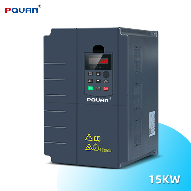
Industrial environments demand precise equipment configuration to ensure operational reliability and worker safety. An inverter serves as a critical component in modern motor control systems, converting direct current or regulating alternating current to optimize motor performance across manufacturing, processing, and automation applications. Proper inverter installation directly impacts energy efficiency, equipment longevity, and system uptime in these demanding settings. Without following established installation protocols, organizations risk equipment failure, unexpected downtime, and potential safety hazards that could compromise production schedules and employee welfare.
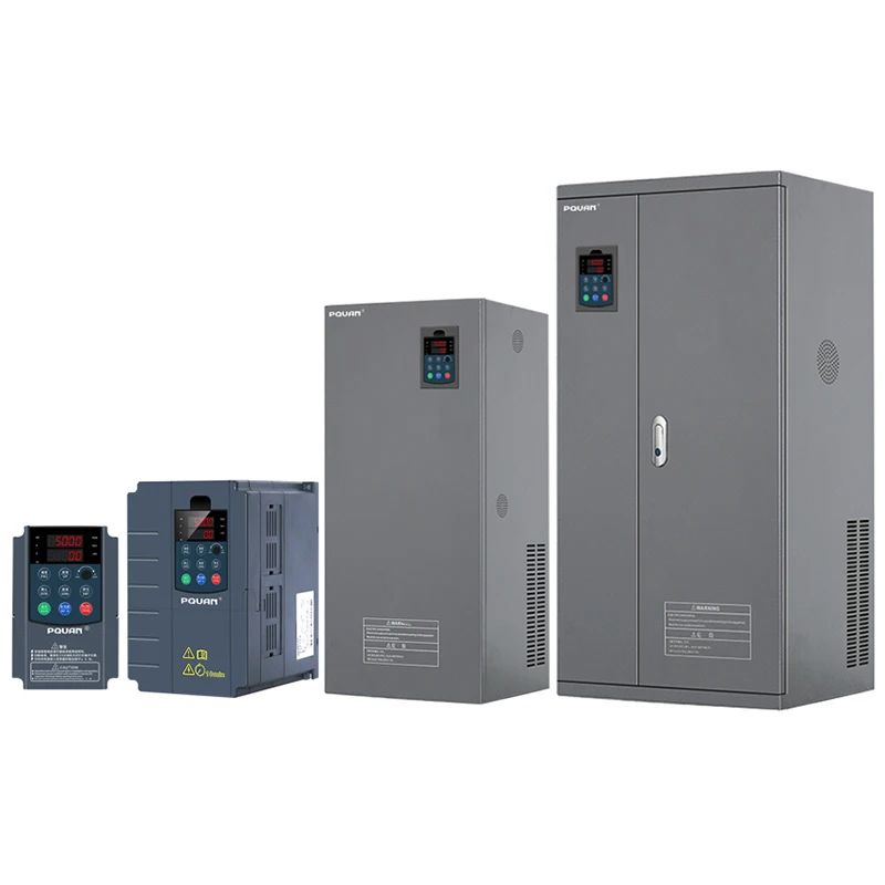
This comprehensive guide explores the essential best practices for inverter installation in industrial environments. Whether you are upgrading existing motor control systems, implementing new automation solutions, or managing preventive maintenance protocols, understanding proper inverter installation techniques ensures your equipment operates at peak efficiency while maintaining safety standards. The following sections detail critical planning considerations, on-site installation procedures, and post-installation optimization strategies that industrial facilities should implement.
Pre-Installation Planning and Site Assessment
Environmental Conditions and Location Selection
Before any inverter installation begins, conduct a thorough site assessment to identify environmental factors that will affect performance. Industrial facilities experience temperature fluctuations, moisture exposure, dust accumulation, and vibration from adjacent machinery. An inverter requires proper ventilation and thermal management to prevent overheating, which directly impacts efficiency and component lifespan. Select installation locations away from direct moisture exposure, excessive dust sources, and intense vibration zones. Ensure adequate airflow around the inverter unit, with clearance specifications typically ranging from 10 to 20 centimeters on all sides depending on the specific inverter model and manufacturer recommendations.
Electrical Load Analysis and Capacity Verification
Accurate electrical load analysis forms the foundation of successful inverter installation. Calculate the total power requirements of all connected motors and equipment, including peak demand during simultaneous operation. The inverter capacity must exceed anticipated load requirements by a safety margin, typically 15 to 25 percent, to accommodate startup surge currents and prevent nuisance shutdowns. Review power factor data, harmonic content specifications, and motor nameplate ratings to ensure the selected inverter can handle your specific industrial application. Consult with your facility electrical engineer to verify that upstream power infrastructure, including transformers and feeder cables, can supply sufficient current without voltage drops exceeding acceptable limits, as inadequate supply voltage severely compromises inverter performance and longevity.
Physical Installation and Electrical Connection
Mounting and Cable Routing Procedures
Mount the inverter on sturdy vertical surfaces using vibration-damping brackets to minimize mechanical stress and electrical noise transmission throughout your industrial system. Ensure proper grounding by connecting the inverter mounting frame to the facility earth grounding system using appropriately sized grounding conductors. Route power cables and control signal wires separately to prevent electrical interference that could trigger false alarms or erratic motor behavior. Power cables should use shielded cable where practical, with shield connections following manufacturer specifications to suppress electromagnetic emissions. When running multiple cables in the same conduit, maintain at least 10 centimeters of separation between high-voltage power conductors and sensitive low-voltage control signals to ensure signal integrity throughout your inverter installation.
Input and Output Wiring Configuration
Proper inverter wiring requires meticulous attention to terminal labeling, conductor sizing, and connection sequence. Match input power connections to the inverter's rated voltage class, confirming that three-phase systems have balanced voltage across all phases within plus or minus three percent tolerance. An inverter with undersized input conductors generates excessive heating and voltage drops that reduce available output power and trigger thermal protection mechanisms. Size output conductors between the inverter and motor using calculations based on maximum inverter output current, not motor nameplate current, since the inverter can deliver higher current during acceleration or fault conditions. Twist output conductors together or route them through common conduit to minimize common-mode voltage stress that could damage motor winding insulation, particularly in systems using long cable runs or multiple motors connected through the same inverter.
Configuration, Testing, and Commissioning
Parameter Programming and System Setup
After completing physical inverter installation, access the control interface to program parameters specific to your motor and application. Configure base frequency settings, acceleration and deceleration ramp times, maximum output frequency limits, and current limits appropriate for your equipment specifications. An inverter's protection features require proper calibration including voltage sensing parameters, thermal overload thresholds, and fault response behaviors that match your industrial facility's safety requirements. Verify resolver or encoder connections if your system uses feedback for closed-loop speed control, ensuring signal continuity and proper polarity before energizing the system. Test the inverter communication protocol if networked systems integrate this equipment into your facility's automation infrastructure, confirming data transmission rates and error checking functions work correctly.
Commissioning Testing and Performance Validation
Perform comprehensive commissioning tests before placing the inverter into full production service. Begin with no-load operation at low frequencies to verify motor rotation direction and confirm that the inverter control signals activate correctly without attached load. Gradually increase operating frequency and monitor voltage, current, and temperature parameters throughout the acceleration cycle, ensuring all readings remain within acceptable ranges defined by equipment specifications. Under loaded conditions, verify that the inverter maintains stable speed control, responds appropriately to load fluctuations, and activates alarm functions if operating parameters exceed safe limits. Document all commissioning measurements and system responses in a baseline report that serves as a reference for ongoing maintenance and troubleshooting throughout the equipment's operational life in your industrial setting.
Ongoing Maintenance and Performance Optimization
Preventive Maintenance Protocols
Establish regular maintenance schedules to keep your inverter operating reliably for extended periods. Schedule quarterly visual inspections to detect loose connections, corrosion, or cable damage that could degrade performance or create safety hazards. Clean dust and debris accumulation from cooling fins and air intake areas using compressed air or soft brushes, as clogged ventilation pathways cause thermal stress that shortens inverter component lifespan. Check helical retaining connectors and terminal blocks periodically, tightening any loose connections using appropriately calibrated torque tools to prevent arcing or intermittent faults that manifest as operational instability. Monitor operating temperature trends using facility monitoring systems, as gradual temperature increases often signal cooling system degradation or environmental changes requiring corrective action.
Troubleshooting and Optimization Strategies
When an inverter exhibits irregular operation or generates fault codes, systematic troubleshooting based on documented installation specifications resolves most issues efficiently. Review fault logs stored in the inverter's diagnostic memory to identify specific failure modes, whether related to electrical parameters, thermal conditions, or control signal anomalies. Verify that facility power supply quality meets specifications, measuring voltage balance, frequency stability, and harmonic distortion that could disrupt inverter operation. Optimize inverter performance through parameter adjustments that improve efficiency, reduce energy consumption, and extend equipment intervals between maintenance services, potentially lowering operational costs significantly. Consider upgrading cooling accessories or relocating the inverter to environments with better thermal management if recurring temperature-related issues persist despite preventive maintenance efforts.
FAQ
What safety precautions are essential during inverter installation?
Always verify that power is disconnected and properly locked out before beginning any inverter installation work. Discharge residual electrical energy stored in capacitors using insulated tools and grounding cables before touching internal components. Ensure workers handling the inverter have appropriate electrical training and understand hazards associated with high-voltage equipment. Install appropriate warning labels and safety signage on the inverter to alert facility personnel about electrical hazards. Use personal protective equipment including insulated gloves and safety glasses when working with electrical connections during inverter installation procedures.
How does cable length affect inverter performance and what measures prevent issues?
Extended cable runs between the inverter and motor increase voltage drops and expose the system to electromagnetic interference that degrades control precision. Keep cable distances below 100 meters where possible, using appropriately sized conductors to minimize voltage loss to acceptable levels typically under 3 percent of nominal system voltage. Install common-mode chokes or output filters on long cable runs to suppress voltage spikes that stress motor insulation and create noise that interferes with adjacent equipment. These protective measures ensure that motor voltage remains stable throughout your inverter installation across variable cable configurations.
What commissioning steps prevent common inverter failures after installation?
Verify motor rotation direction before connecting load, as incorrect rotation direction may damage driven equipment or create safety hazards in your facility. Check acceleration and deceleration ramp settings to ensure smooth operation that prevents sudden mechanical shocks capable of damaging mechanical components. Confirm that all alarm and protection functions activate correctly at calibrated thresholds, ensuring the inverter protective functions work as designed during actual operating conditions. Validate that control signal connections respond correctly to command inputs across the full operating range, confirming system integration functions properly after inverter installation completion.